Blowering Dam Construction
BUILDING OF DAM OPPOSED - ALBURY (N.S.W.), Tuesday. - Members of the Tumut Agricultural and Pastoral Association declared recently that if the Darbalara dam was constructed it would ruin the town of Tumut, which would soon be deserted. The water they said, would back up almost to the town, the richest land in the Tumut Valley would be destroyed, and the Tumut Co- operative Butter Factory would be closed.
Members of the association discussed the subject at their last meeting, and decided to urge the Water Conservation and Irrigation Commission to abandon boring operations at Darbalara. - (Ref- The Argus (Melbourne, Vic. : 1848 - 1957)(about) Previous issue Wednesday 13 June 1934 Page 8).
On the 21st March, 1952, some 15 acres of land from Portion No.... at a fee of Pounds ? was resumed from Mrs B E Long. To establish an Office - Store - Workshops - Camp - Housing for the preparation to commence construction of the "Blowering Dam".
The establishment of the work site plus investigation drilling and soil testing was carried out until 1957 when due to lack of finance work was stopped temporarily. It did not recommence until 1963 when the decision was made to have the Snowy Mountains Authority build the Blowering Dam as agents for the Water Conservation and Irrigation Commission (W.C. & I.C.).The W.C. & I. C. was given the responsibility of administration of the Land Resumptions.
N.S.W. resumes - 18,000 acres - for Blowering - SYDNEY. Thursday. — The N.S.W. Government will resume 18,000 acres of private land adjoining the storage area of the Blowering Dam at Tumut.
It will use the land for tourist parkland.
The resumptions were announced today by the Minister for Agriculture and Conservation, Mr. Enticknap.
The Snowy Mountains Authority expects to complete the dam by late 1968.
In addition to acquiring the land which would be submerged the Government would resume 9,000 acres of private land on the eastern side of the storage and add it to the Kosciusko State Park.
On the western side of the storage lake another 9.000 acres of land would be resumed and dedicated as a State forest under the control of the Forestry Commission.
"The commission intended to establish a pine plantation on the southern part of this land. - Mr Enticknap said the land was being resumed primarily to protect the storage from siltation. The soil Conservation Service would carry out soil erosion preventive works. - (Ref- The Canberra Times (ACT : 1926 - 1995)(about) Previous issue Friday 15 January 1965 Page 3).
BLOWERING DAM - DRILLING.TENDERS In envelopes endorsed "Blowering Dam Drilling" and. addressed to the Secretary. Water Conservation and Irrigation Commission, Box 2708. G.P.O., Sydney, will be received from experienced and capable Diamond Drilling Contractors, up to 10.30 a.m. on Thursday. 17th July. 1952. for the execution of 4000 feet of core drilling at the site of Blowering Dam. nine miles south of Tumut. Specifications and Conditions of Tender may be Inspected at the Commission's Plan Room In the basement of the Agriculture Building. Farrer Place Sydney. J. O'BRIEN. Secretary. (51/14709.) - (Ref- The Sydney Morning Herald (NSW : 1842 - 1954) Saturday 21 June 1952).
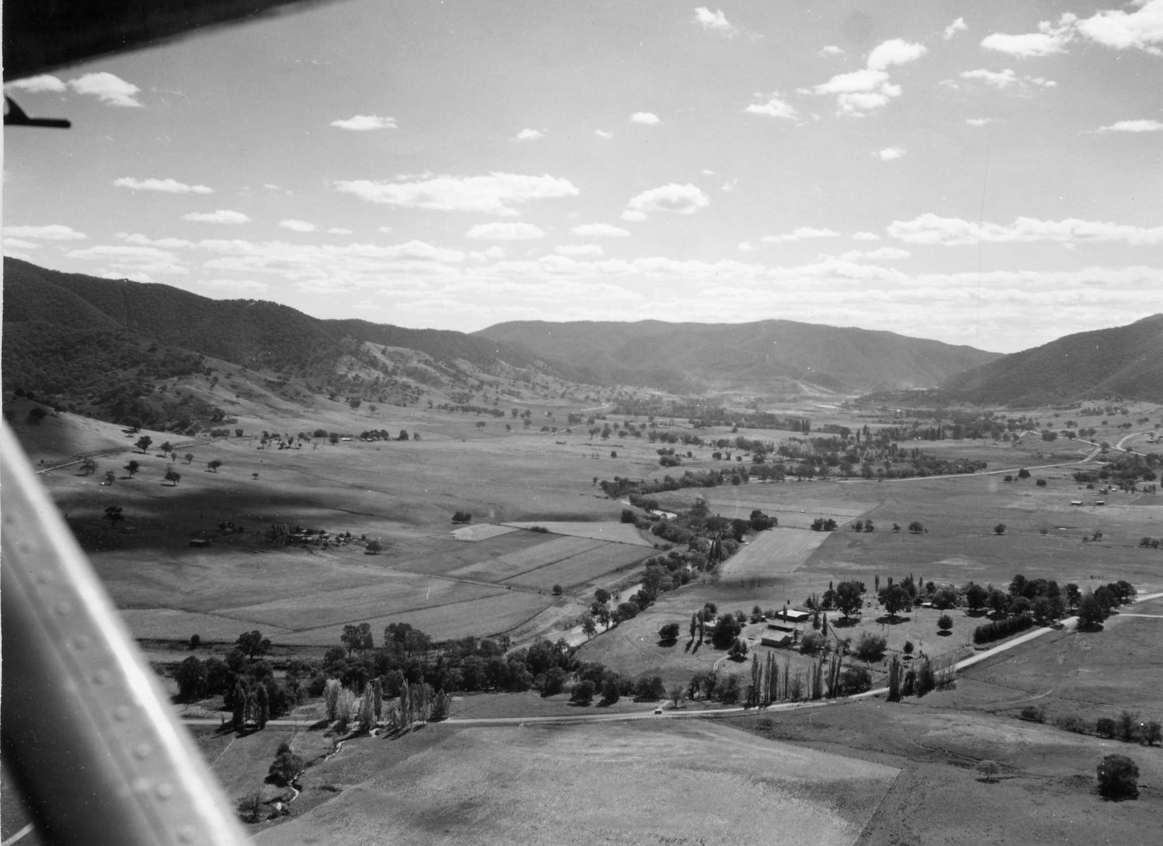
1. Looking back to the wall. See Blowering Station, Hampstead, Symons, Bourke and Halloran properties on the east side. Leo and Colin Myers, Cranes, Davis, Eggleton and Stanfield properties on the West side of the Tumut River.
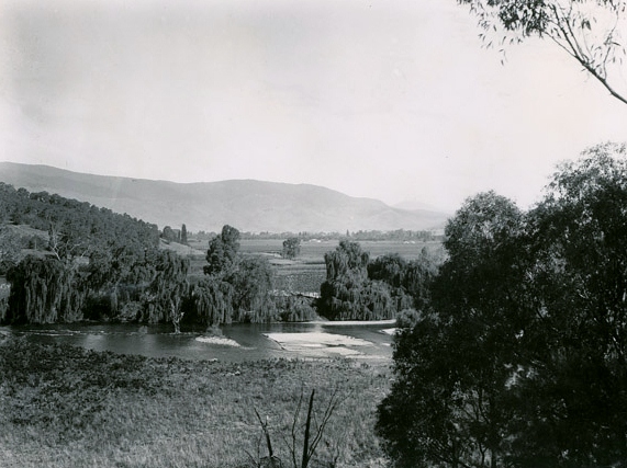
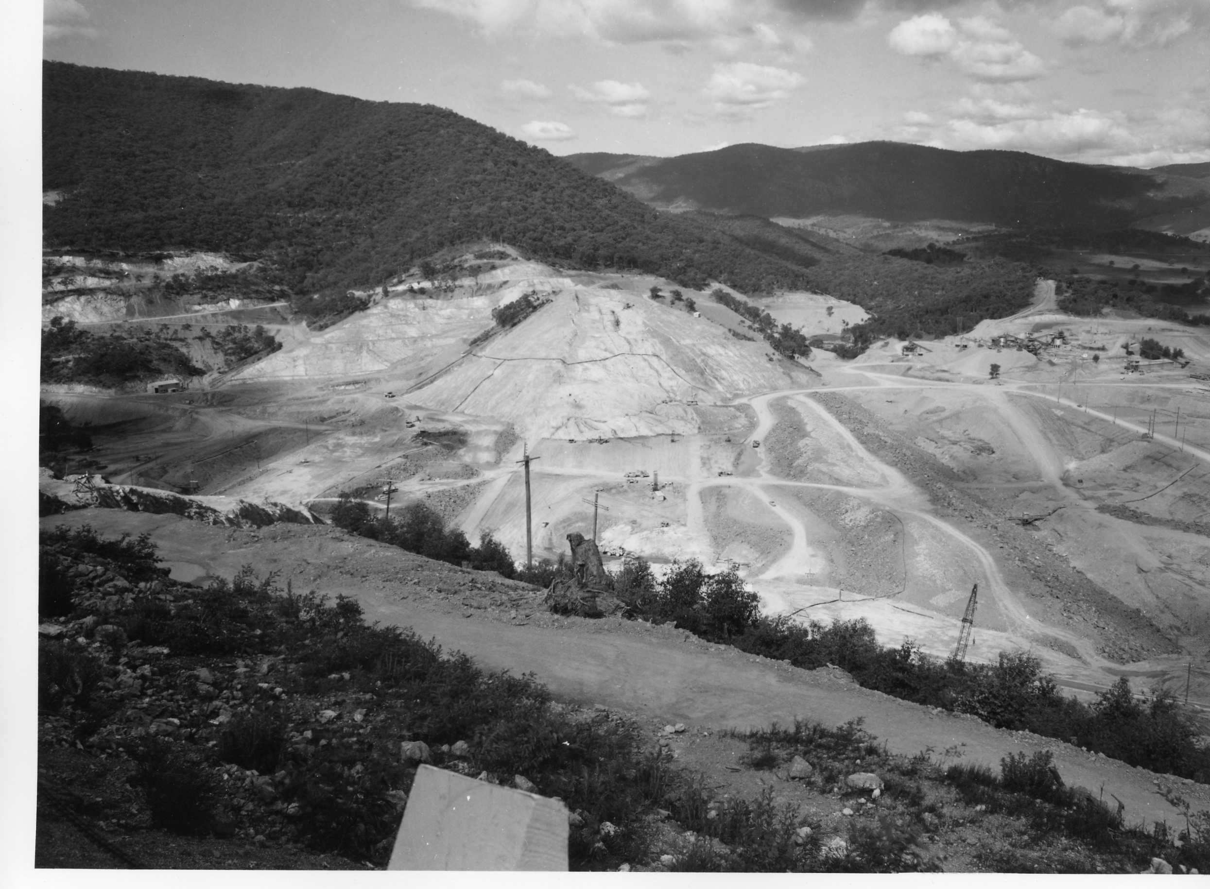
3. Looking back up the Tumut River towards Blowering Station Homestead. They cleared these trees and flooded this valley for a rock wall!!
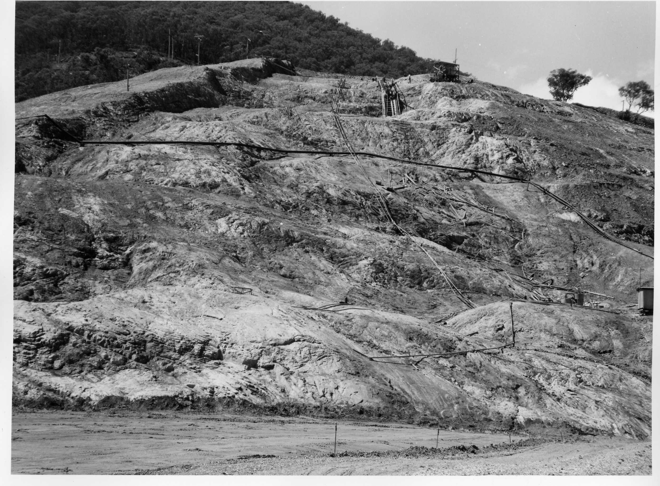
4. Clearing the way down the east bank. See traces of the Monaro Highway. The Tumut River has been diverted.
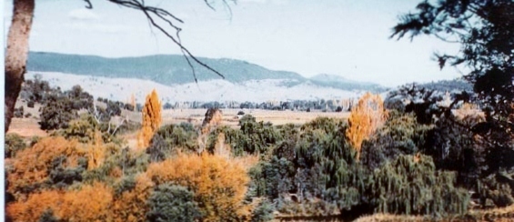
5. A portion of Stanfield's Millet Crop, which is now under the wall - looking south.
 ..
..
6.
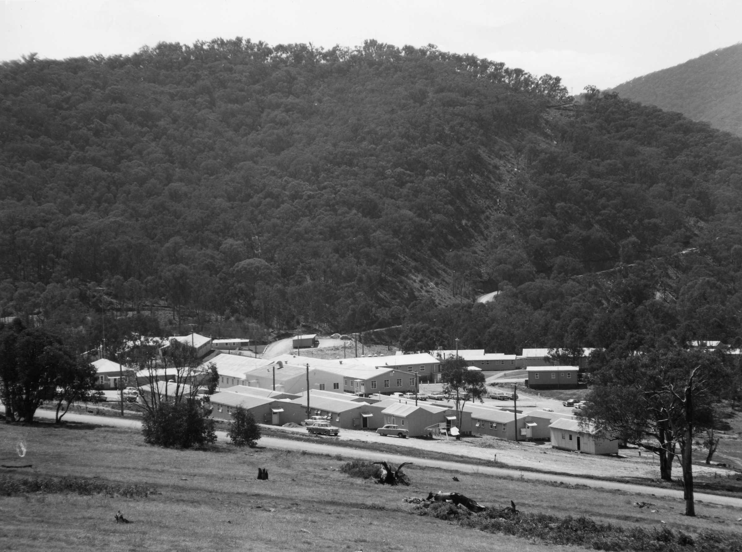
7...They set up a great camp site at West Blowering. With dam wall diversion road.
8. A portion of Stanfield's Millet Crop, which is now under the wall - looking south.
9 This photo looking slightly to the right from the one below
 .
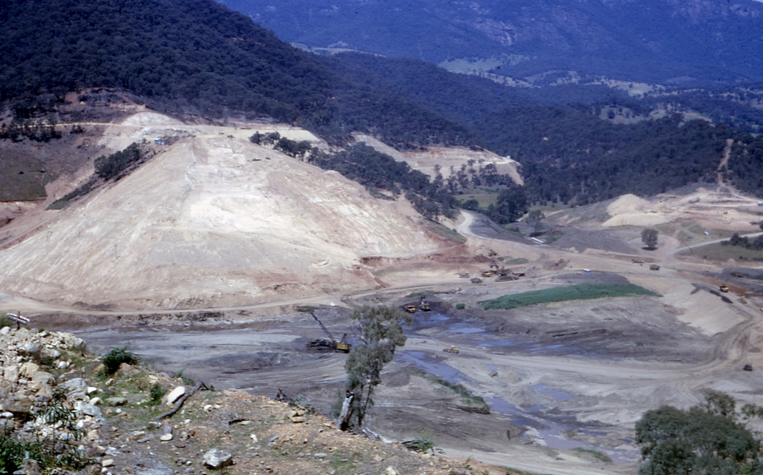
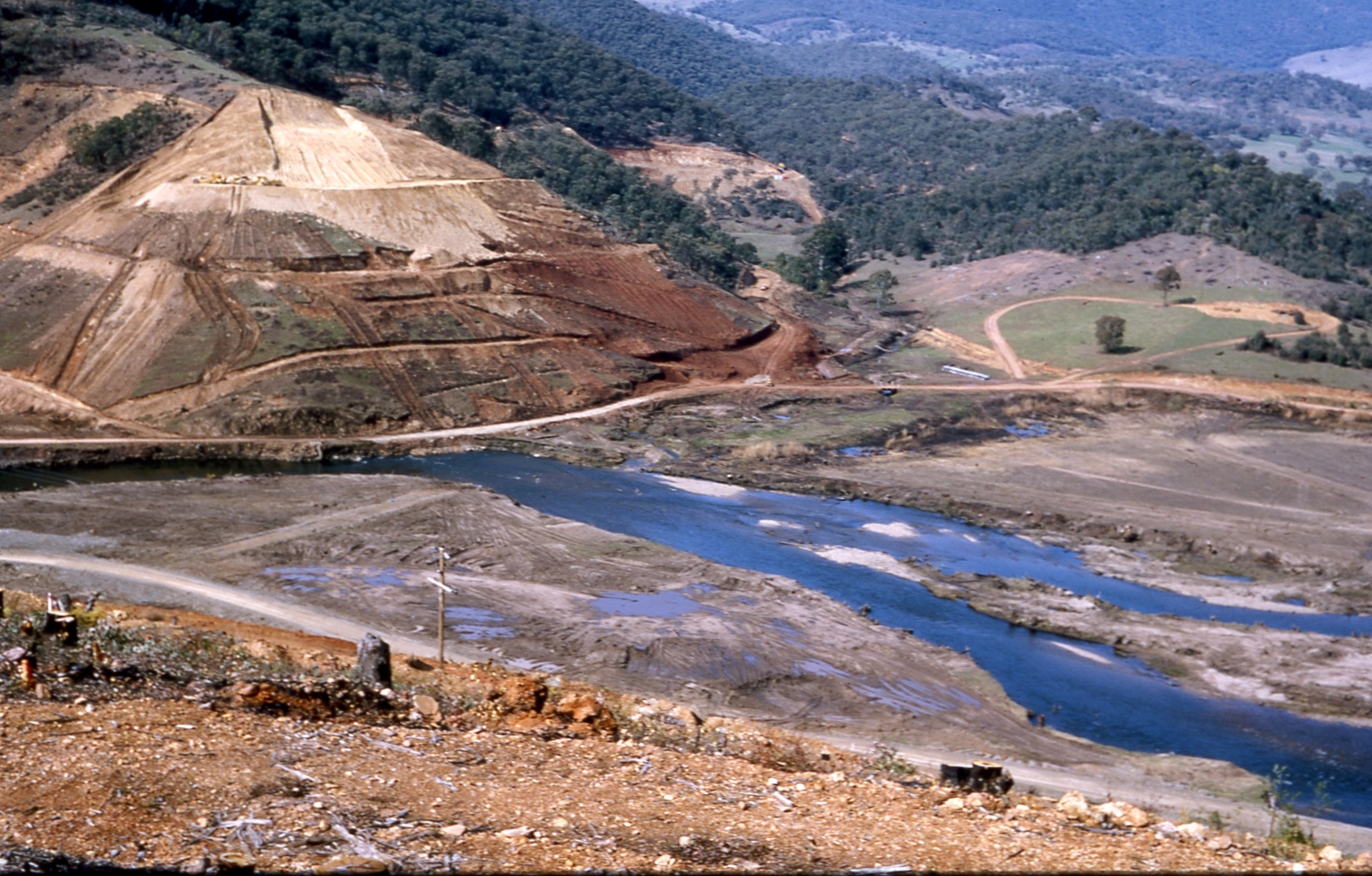
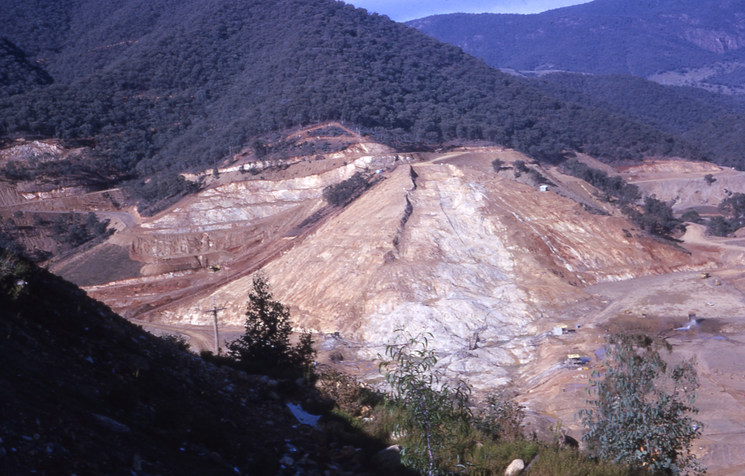
. 10. Here Stanfields Paddocks are cleared the Old Monaro Highway is still partialy visable the Eastern Foundation wall is starting to develope. You will notice in the rear left bacground the Spill Way is being cleared also.(Just below the Tree Line).

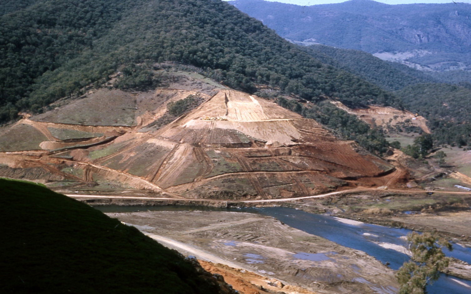
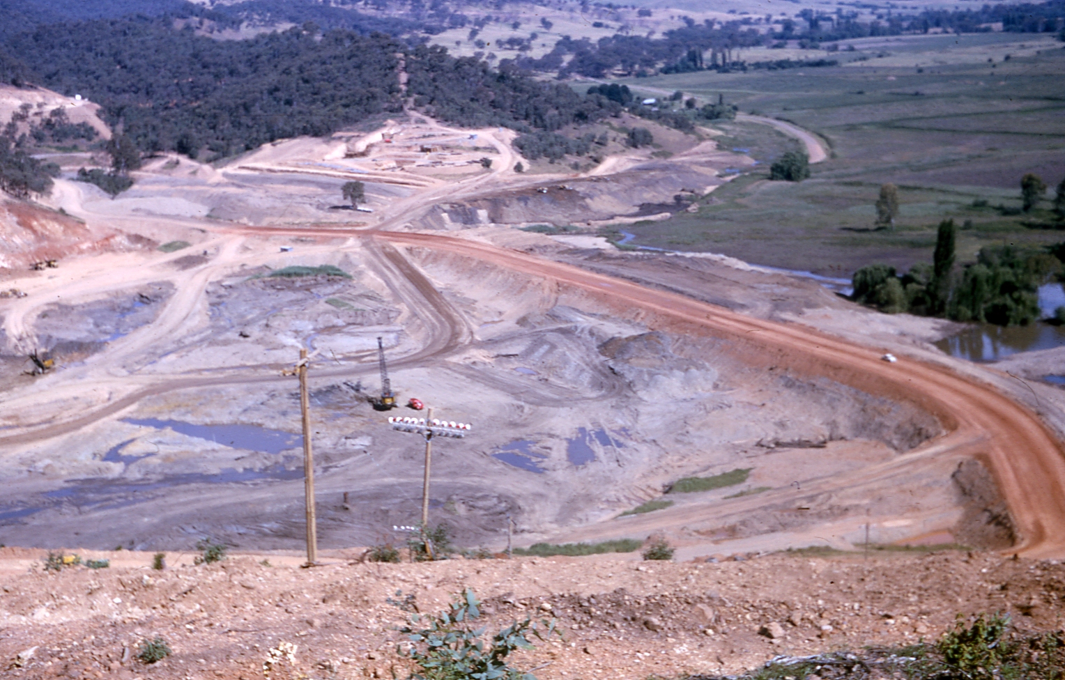
13. Tumut River now diverted and wall foundations coming over to West Wide..
14
15
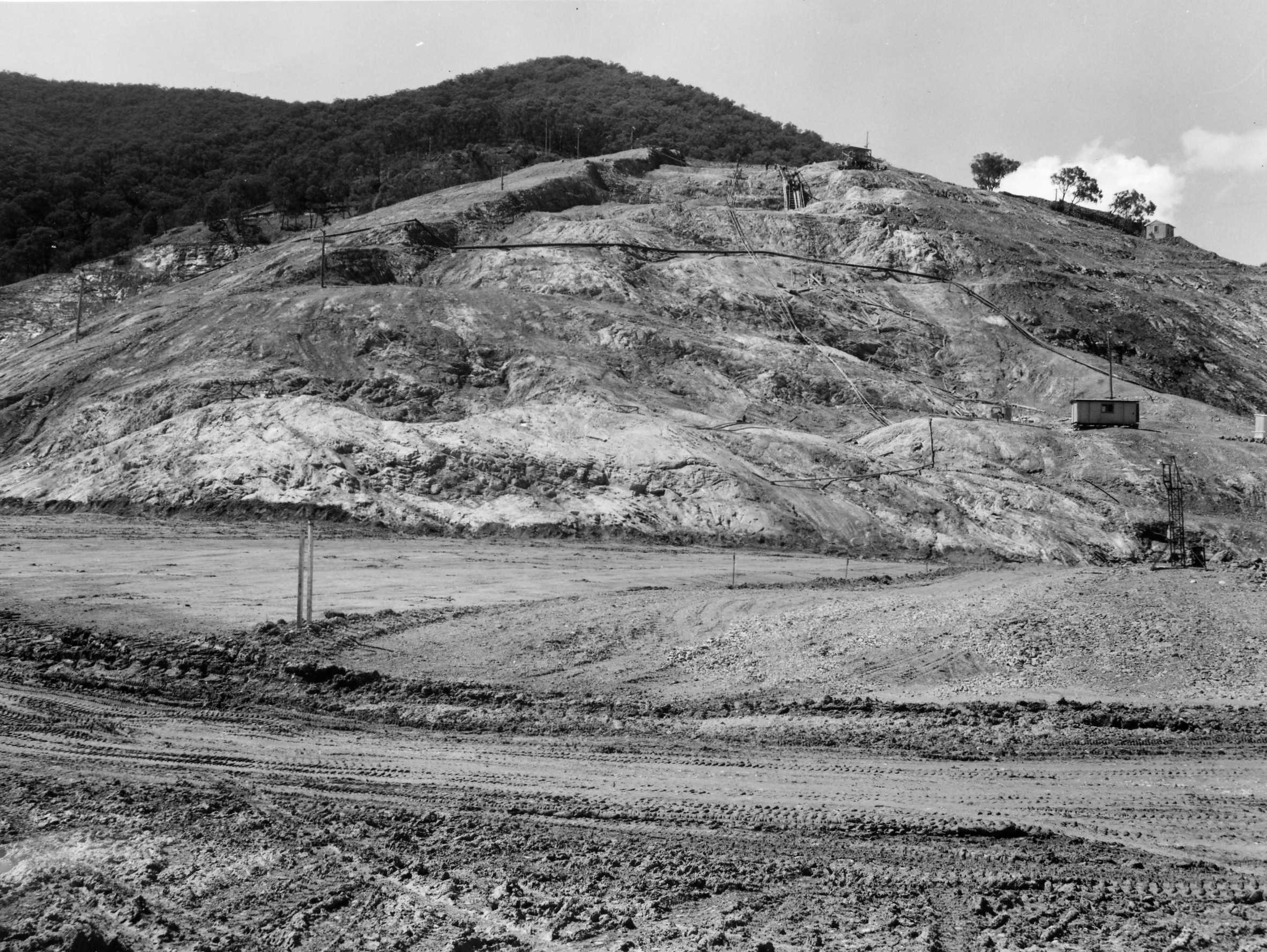
16. Clearing the way down the east bank to the flats.
17 See below what was cleared for these foundations, to flood the fertile valley.
18. Clearing the way down the east bank to the flats.
 .
. 19.
20. See on the flats near the workings, a white building that is Patrick (1st) Halloran's house. Bourkes flats etc.
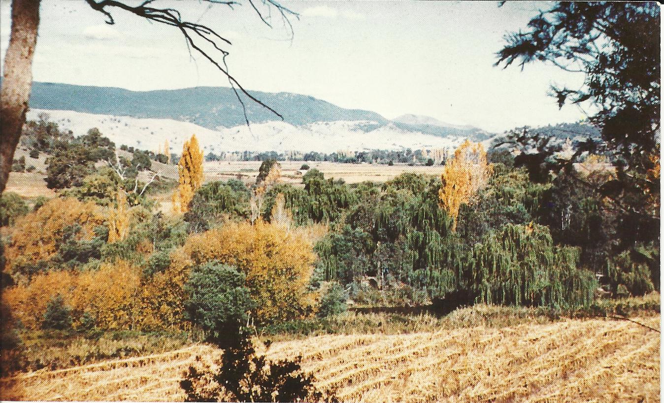
21. Stanfield's farming flats in very early days. Looking across the Tumut River to the Johnson - Bridle clear hill and house.
22
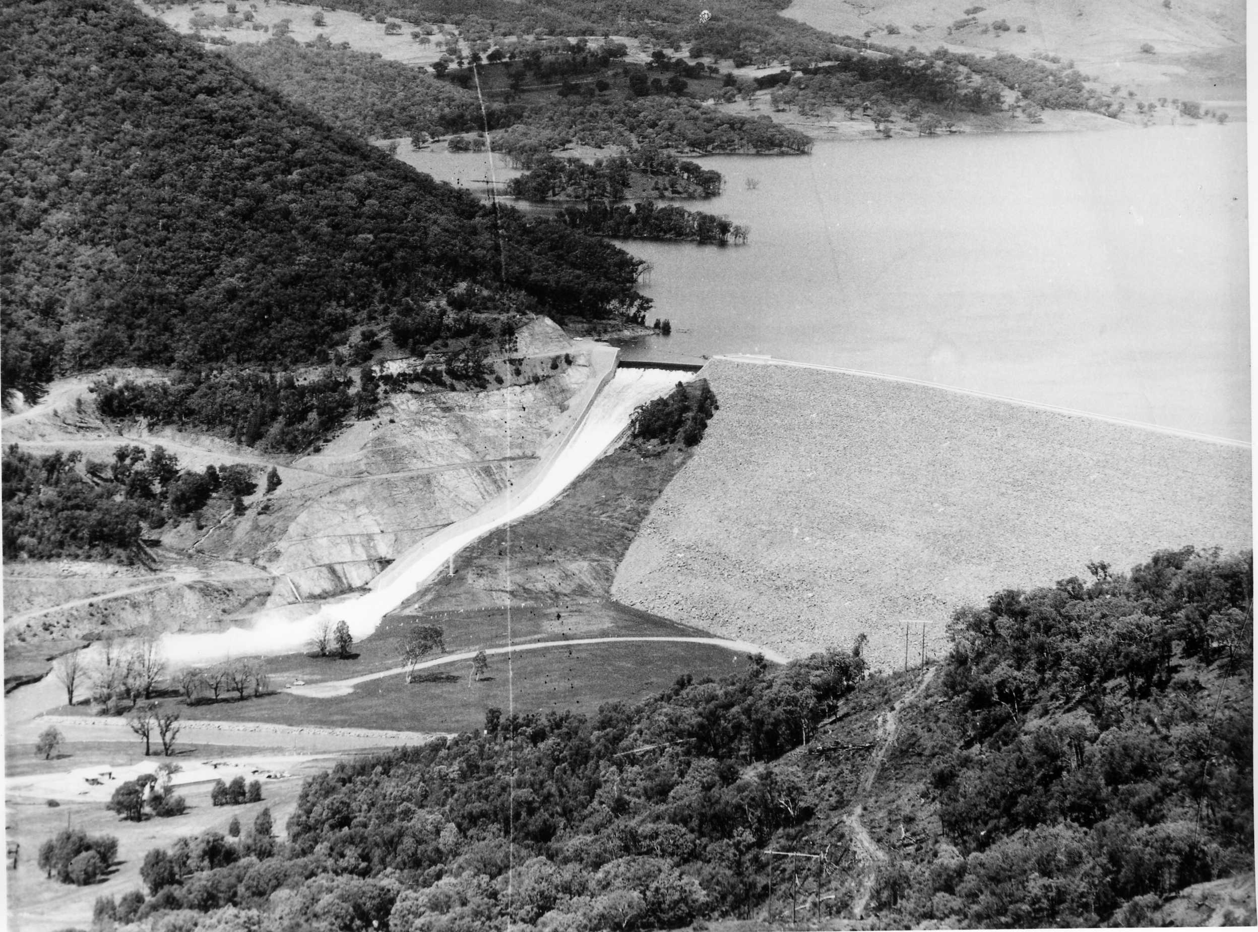
23. From this to ... To - Finished and full to overflowing.Looking at Dam Wall from North West.
The Snowy Mountains Hydro-electric Scheme (SMHES) is very large, covering 7 780 square kilometres. The original purpose of the SMHES was to:
collect, regulate, and use the waters of the southward flowing Snowy River and other streams in the Snowy Mountains for generating large quantities of peak load electricity for New South Wales, Victoria and the Australian Capital Territory supplement the westward flowing Murray and Murrumbidgee Rivers to enable expansion by irrigation of primary production on the dry but fertile plains of the Murray and Murrumbidgee region.
The Scheme operates entirely within the parameters of its enabling legislation, the Snowy Mountains Hydro-electric Power Act 1949 and the Schedule added in 1957. (SMA, 1993: 8)
16 dams
7 power stations
145 kilometres of tunnels
80 kilometres of aqueducts
and access roads were cut through the mountainous country. There were many construction records set and broken on the Scheme.
Bridges
Three types of bridge were built by the Snowy Mountains Hydro-electric Authority (SMA):
reinforced concrete or steel girder
Bailey, timber or composite
timber span or suspension.
Most bridges in use are concrete or steel girder. Bailey bridges were originally designed as portable and usually temporary bridges. One suspension footbridge has been retained at Geehi Outlet.
Suspension bridge (SMA, 1992)
Dams are perhaps the most prominent above ground civil structures on the Scheme. There are sixteen dams spread over the Scheme with a total storage capacity estimated to be about thirteen times the volume of Sydney Harbour.
Satellite image of location of dams (SMA, 1993: 9)
There are five principal types of dam, these terms refer to the chief materials used in the construction of the dam wall:
Rockfill an embankment dam dependent for its stability primarily on rock, usually containing selected impervious earth and filter
zones, with more than 50% of its volume composed of compacted or dumped rockfill . (SMA, 1993: 69)
Earthfill an embankment dam consisting of less than 50% rock and mostly constructed of compacted impervious earth and filter materials in zones and protected by outer zones of rock. (SMA, 1993: 17) View image of Eucumbene Dam
Concrete gravity a concrete mass dam, which can be straight or curved in plan (SMA, 1993: 51) View image of Tumut 2 Dam
Concrete arch also a concrete mass dam. It is curved in plan with the convex (bulging) curvature on the upstream face. Designed so that most of the loads due to water pressure are carried to the abutments by arch action.
Section through Tumut pond dam (SMA, 1993: 40)
View image of Tumut pond Dam
Slab and buttress a concrete dam constructed with thin walls or buttresses perpendicular to the axis which support a flat slab of reinforced concrete that forms the water barrier. There is one slab and buttress dam on the Snowy Mountains Hydro-electric Scheme on Outstation Creek to divert water into the Tooma-Tumut tunnel. (SMA)
The most common type of dam on the Scheme is the concrete gravity. Six dams are constructed in this way.
The highest dam on the Scheme is Talbingo, a rockfill dam, at 161 metres. The lowest is Khancoban, an earth- fill dam, at 18 metres. Eucumbene Dam has the largest reservoir capacity and Deep Creek the smallest.
Lake Eucumbene is the largest reservoir in the Snowy Mountains Scheme. It holds approximately nine times the amount of water contained in Sydney Harbour and covers more than 14 500 hectares. Lake Eucumbene collects water from the Eucumbene, Upper Murrumbidgee and Snowy Rivers and its enormous capacity is central to the flexibility of the Scheme to generate electricity and provide irrigation waters.
An earthfill dam Eucumbene Dam, one of only three earthfill dams on the Scheme, holds the water of Lake Eucumbene. The other earthfill dams are at Khancoban and Tooma. Eucumbene Dam stands 116 metres high and is 686 metres thick at its base. The outer walls of the dam are built of rock while the inner core is compacted, impervious clay.
Eucumbene Dam specifications
Type
Height
Crest length
Base width
Crest level Earthfill
116.1m
579.1m
686 m
RL 1 1683.43m Spillway
Type
Capacity
Crest length
Crest level
Overflow ski-jump and bucket with two vertical lift gates, each 6.70m wide by 3.90m high
475 m3/s
13.4m
RL 1 161.30m
Volume of embankment
Earthfill Filter Rockfill Total 3 810 800m 31 088 300m 31 836 200m 36 735 500m3 River outlet works 0.15m diameter bypass to provide Eucumbene Cove water supply. Tunnel drainage valve modified for riparian right releases of 0.07 m3/s.
Foundation Closely jointed hard siltstone and quartzite with overburden of decomposed rock and slope-wash up to 6.10m deep. Other features Subsidiary embankment containing 121 900 m3 of fill across a low saddle in a ridge forming the left abutment.
Reservoir
Gross Capacity
Active Capacity
Area at full supply level (FSL)
4 798 400 x 103m3
4 366 500 x 103m3
14 500 ha Construction period May 1956 to May 1958 (the gated spillway was constructed under a separate contract in 1977-78)
Section through Eucumbene Dam (SMA, 1993: 17) Plan of Eucumbene Dam (SMA, 1993: 18) Plan of Eucumbene Dam Spillway (SMA, 1993: 18)
Constructing the dam
Before the dam could be built, the waters of the Eucumbene River had to be diverted around the site of the dam wall. The diversion tunnel was constructed through the side of the valley by the Australian company Allied Constructions. This mid-1950s photograph shows the river flowing through the end of the diversion tunnel on the left while the dam wall takes shape in the background. Photo: Bayram Ali (Powerhouse Museum Collection)
The water intake tower, shown partially completed in the photograph below, stood at the beginning of the diversion tunnel. With the completion of the dam, the tunnel still permits the release of small amounts of water down the Eucumbene River. Photo: Bayram Ali (Powerhouse Museum Collection) While work on the wall and intake tower proceeded, the hillside that would form the reservoir basin was cleared of trees. This was necessary to prevent damage to the intake tower from plant material. This photograph shows a bulldozer clearing the forest that covered the Eucumbene River valley. Photo: Bayram Ali (Powerhouse Museum Collection) To minimise seepage and maximise dam strength, the ground at the edge and base of the dam wall was reinforced by grouting. Holes were drilled with machines such as the one below and filled with concrete. Photo: Bayram Ali (Powerhouse Museum Collection) The core of the dam wall was built up slowly with compacted clay to prevent seepage. This was carried out primarily by the sheep's foot rollers shown in this photograph. They are being pulled by International TD-24 bulldozers, which were used throughout the Scheme.
The clay was excavated from a soil quarry downstream of the dam wall and carted to the site in trucks and earthmovers. Photo: Bayram Ali (Powerhouse Museum Collection)
Tunnels
Approximately 98% of the Scheme's engineering features are underground. Tunnels and pipelines, dug deep under the Snowy Mountains, measure 145 kilometres, and with 80 kilometres of aqueducts, collect and divert the inflows of the Snowy Mountains area.
Overview of tunnel features (shown in order of length)
Tunnel Length km Excavated section metres Lined section metres Percentage lined Year of completion Eucumbene-Snowy Eucumbene-Tumut Murrumbidgee-Eucumbene Snowy-Geehi Tooma-Tumut Murray 1 Pressure Tumut 2 Pressure and Tailwater Jindabyne-Island Bend Guthega Murray 2 Pressure Tumut 1 Pressure Tumut 1 Tailwater 23.5 22.2 16.6 14.5 14.3 11.8 11.3 9.8 4.7 2.4 2.4 1.3 6.30 x 6.35 6.91 3.35 x 3.35 6.30 x 6.30 3.79 x 3.71 - - 3.96 x 3.96 5.87 x 5.74 - - 8.53 x 7.77 6.10 x 6.10 6.40 3.10 x 3.10 6.10 x 6.10 3.43 6.93 x 6.93 6.40 3.76 5.26 x 5.05 7.47 x 7.47 6.40 7.93 x 7.49 19.7 28.3 17.7 13.3 20.0 100 100 10.6 11.6 100 100 54.5 1965 1959 1961 1966 1961 1966 1961 1968 1955 1969 1959 1959 Summary of principal features (in SI Units) - tunnels (SMA, 1993: 172)
Specifications of Eucumbene-Tumut tunnel (SMA, 1993: 25) Plan of Eucumbene-Tumut tunnel (SMA, 1993: 25) Profile of Eucumbene-Tumut tunnel (SMA, 1993: 25) Tunnel cross-sections (SMA, 1993: 55)
The longest tunnel is the Eucumbene-Snowy at 23.5 kilometres. This tunnel diverts the water of the Snowy River from Island Bend Pondage to storage in Lake Eucumbene, and when required returns the water to the Snowy-Geehi Tunnel at Island Bend. It took four years to build the tunnel, a remarkable achievement when it is realised that the geology of the Snowy Mountains is predominantly granite and the diameter of the tunnel at maximum is 6.30 metres.
World tunnelling records were established on the Scheme. In 1961, the Australian firm Thiess Bros, were contracted for the Geehi section of the Snowy-Geehi tunnel. In 1963, the firm established the world record for hard rock tunnelling when 165 metres of tunnel was formed in a week.
Swift progress in tunnelling was the result of many factors, but two deserve a special mention:
the sliding tunnel floor and rock bolting. Sliding tunnel floor The sliding tunnel floor comprises a large sectionalised steel working floor platform, which carried rail tracks, points and crossings, drilling gantry and other tunnelling equipment. A hydraulic jacking system moves each of the three floor units forward in six stages. (Raymond, 1999)
Rock bolting
Rock bolts were used to support the roof and walls of major structures such as tunnels and power stations. Steel bolts, of different length and spacing, were inserted into the rock where they were found to be an excellent anchorage for the rock.
Rock bolts were tension bolts, that when placed, compressed broken or jointed rock surrounding the tunnel and converted the rock into a self-supporting arch structure. The technique of grouting, between the bolt and the rock, was developed for upward sloping bolts. It is claimed that the Snowy engineers developed the world's first successful method of grouting the holes between rock and bolt.
Expansion shell bolt. Adapted from (SMA, 1959: 2)
1. List a range of hardware items that can be used to join masonry or support loads in rock. State the advantages and disadvantages of each support mechanism. 2. Make labelled freehand sketches to illustrate how these support mechanisms work.
Power stations The seven power stations (two of which are underground) house the large generators and turbines that produce the electricity from water that is stored in the Scheme's ponds and reservoirs. Power from the Snowy Mountains Scheme is transmitted at 330kV to the electricity systems of NSW, Victoria, the ACT, SA and Queensland. The Scheme can generate 3 756 megawatts, representing about 17% of the generating capacity of South Eastern Australia. Lower Tumut Switching Station at Talbingo in the final stages of construction. Since 1973 this facility has redistributed the power generated at nearby Tumut 3 Power Station to Victoria and NSW along 330 000 volt transmission lines. Photo: Bayram Ali (Powerhouse Museum Collection)
Towns
Towns like Eaglehawk, Sue City, Happy Jacks and Bella Vista were purpose-built to service specific projects. Home to hundreds or even thousands of people for several years, they were dismantled after work was completed. There were eight major townships. This photograph depicts a street of houses for workers' families at Eaglehawk near the Eucumbene Dam site in winter in the mid-1950s. The town was built by the NSW Public Works Department, which began the Eucumbene Dam project. These buildings were prefabricated in Sydney by Frank R. Wolstoneholme Pty Ltd and transported to the Snowy by semi-trailer. Unfortunately they were not specifically designed for use in the freezing climate of the Snowy Mountains. External water pipes froze in winter and the lack of insulation and double-glazing added to the discomfort in cold weather. Photo: Bayram Ali (Powerhouse Museum Collection)
The Web
Search this website only